Helpline : +91-22-6798 7022
Our Product
- INDFOS

- ROTEX
- SWITZER
- GAUGES
- AUTO DRAIN VALVE
- FLOW METER
QUALITY
| Our key directive is complete customer satisfaction. | |
| We provide our customers with technical support and recommend the product that will suit their requirements. | |
| To verify that the supply made to our clients exact specifications. These are the key to SUNBEAM INDUSTRIES continued growth. | |
DIFFERENTIAL PRESSURE INDICATOR — SWITCH

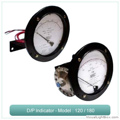
MODEL 120 / 180
![]() FILTRATION
FILTRATION
![]() FLOW
FLOW
![]() LEVEL
LEVEL
![]() UNIQUE MAGNETIC POINTER MOVEMENT
UNIQUE MAGNETIC POINTER MOVEMENT
![]() PRESSURE MEDIA ISOLATED GAUGE
PRESSURE MEDIA ISOLATED GAUGE
SWITZER Differential Pressure Indicator has a rugged design for industrial use to measure the differential pressure in a filtration system or across a flow orifice or level in a tank and indicates directly on a single gauge dial.
A specially designed magnetic movement allows the instantaneous sensing of both pressures while completely isolating the gauge function from the pressure chamber without the use of mechanical seals.
Unlike ordinary differential pressure gauges, these instruments can be supplied with switching facility (a reed switch in Model 120 / 122 and a microswitch in Model 180) to initiate an alarm signal or system shutdown. One or two switches can be fixed to open or close on either rising or falling differential pressure. Switch setting is easily made through an external adjustment.

MODEL 105 & 106 :
![]() MID-WEST, USA DESIGN
MID-WEST, USA DESIGN
![]() CAPSULE / BELLOWS SENSOR
CAPSULE / BELLOWS SENSOR
![]() HIGH OVER RANGE
HIGH OVER RANGE
![]() HI-LO SWITCHING
HI-LO SWITCHING
![]() 270 DEG. POINTER TRAVEL
270 DEG. POINTER TRAVEL
![]() FLOW OR LEVEL MEASUREMENT
FLOW OR LEVEL MEASUREMENT
SWITZER style 105 / 106 sensor unit consists of an assembly of sensitive multiple diaphragm (capsule) or bellows which responds to differential pressure across it.
A free spring torque tube, a unique yet time proven device, senses the motion of element in contact with the process medium and transfers it to a precision friction free pointer movement mechanism in the gauge case through the wall of the pressure housing.
Unreliability of leak due to wear of ‘O’ rings encountered in conventional motion transfer shaft systems is totally eliminated, as the torque tube with its welded construction provides a perfect high pressure seal between the process and the gauge case.
Alarm switching is provided through snap acting SPCO microswitch. One microswitch for a single high or low alarm or two microswitches one each for high and low alarms are possible.
Model 105 / 106 indicators are available with ranges 0 – 10 InWC to 0 – 1.6 Kg/Cm² in different engineering units. Indicators with centre zero / bi-directional ranges and liquid filled dials are possible. Refer range tables for details.
Higher DP ranges for 0–1 to 0–350 Kg/Cm² are available in Model 109.
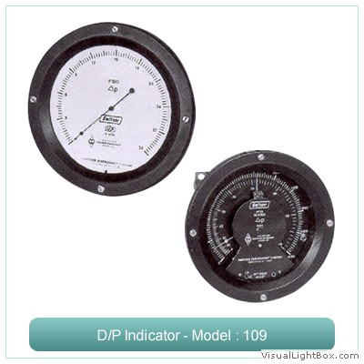
STYLE 109 :
![]() MID-WEST, USA DESIGN
MID-WEST, USA DESIGN
![]() BOURDON SENSOR
BOURDON SENSOR
![]() HIGH OVER PRESSURE
HIGH OVER PRESSURE
![]() 270 DEG. POINTER TRAVEL
270 DEG. POINTER TRAVEL
![]() ONE OR TWO VISIBLE SET POINTERS
ONE OR TWO VISIBLE SET POINTERS
![]() POWER SUPPLY OPTIONS
POWER SUPPLY OPTIONS
![]() OPTIONAL DEAD BAND ADJUSTMENT
OPTIONAL DEAD BAND ADJUSTMENT
Switzer style 109 Differential Pressure Indicator is powered by a test gauge quality Bourdon tube assembly. It is encapsulated in a high pressure chamber fitted with a pressure connection to the inside of the Bourdon tube and a second connection to the pressure chamber. The Bourdon assembly indicates the difference in pressure applied inside and outside the Bourdon tube.
The volume displacement of the Bourdon tube is near to zero (0.02 cc); so the speed of response of the indicator to change in differential is instantaneous even on low volume pressure system. The low volume displacement is an important advantage for differential pressure leak detection.
The output shaft of the Bourdon sensor is magnetically coupled through the solid wall of the pressure chamber to a sensitive jewelled pointer shaft in the dial housing outside the pressure chamber. The solid separation wall eliminates the requirement of a separate blow-out disc in the gauge case.
The Differential Pressure Indicator can be provided with alarm switching facility through an electronic “Locked Logic Alarm Control” Switching (LLC). This is an all solid-state switching facility available with one or two set points.
The “Locked Logic” concept provides a control system which has a two step latch-lock control action, for a positive locked control above and below the set point. The control action is fully protected against electrical disturbances.

MODEL 106 D :
![]() DIAPHRAGM SENSOR
DIAPHRAGM SENSOR
![]() WEATHERPROOF
WEATHERPROOF
![]() HIGH OVER PRESSURE
HIGH OVER PRESSURE
![]() 270 DEG. POINTER TRAVEL
270 DEG. POINTER TRAVEL
![]() HI – LO SWITCHING
HI – LO SWITCHING
![]() FLOW OR FILTER MONITORING
FLOW OR FILTER MONITORING
SWITZER 106 D range of Differential Pressure Indicators
are 316 Ti SS diaphragm operated to ensure reliable
indication of pressure difference between two inputs.
High and low pressures are applied on either side of a
single diaphragm. The resultant deflection is transferred
to the gauge case through a unique motion – transfer
mechanism and a SS movement. The volume displacement
is kept minimum to achieve high repeatability. The pointer movement and dial are fitted in a weatherproof die cast
aluminium or SS case. Snubbers are part of the process
connections, which protect the instrument from process
pressure fluctuations.
High and Low switching for alarm can be provided with
adjustable cam mechanism to actuate one or two
microswitches. The diaphragm is protected fully from over
pressure through a seal valve assembly.


Designed By Galagali Multimedia Pvt. Ltd.
blog.sunbeam.com
news.sunbeam.com
articles.sunbeam.com